HP5065A Power Supply Simplification
The HP5065A has a power supply quite typical for old-ish time/frequency equipment: A transformer+rectifier for plugging into a wall-outlet and a 24V nomial DC input for battery backup.
Option 2 provided a small internal battery which probably was most handy while moving the 5065 between labs or while moving cables, but I’m ignoring that, my unit doesn’t have it, and if it had I would remove it, since the batteries would be long dead.
The input side of the power-supply therefore looks like this “summary” of the relevant schematics:
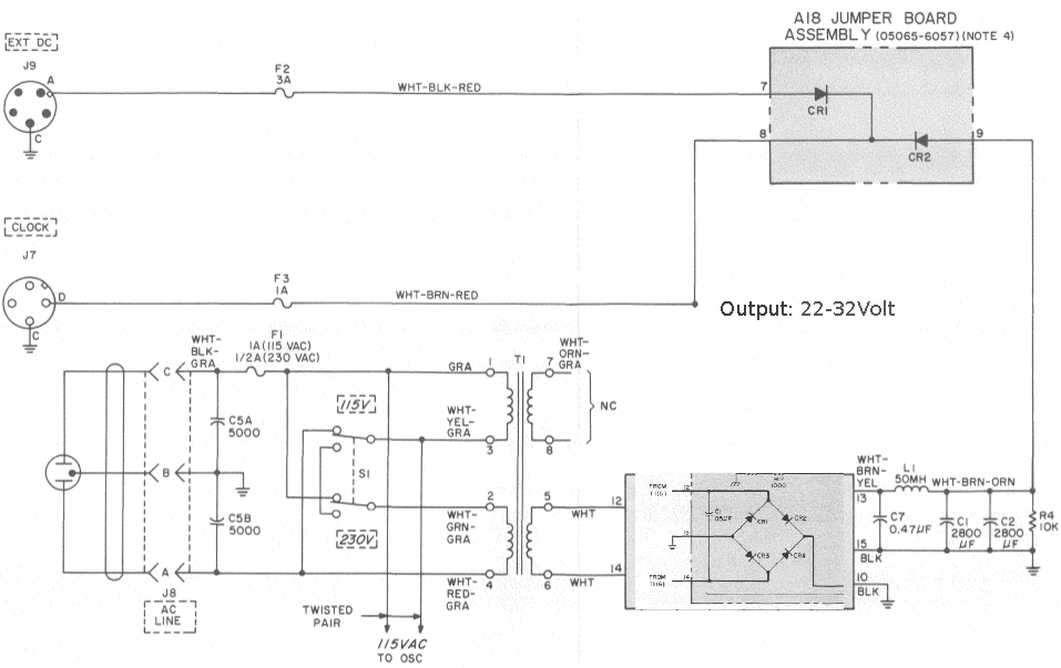
There are some details worth noting:
The “115VAC TO OSC” connection at the botton is for the 00105 OCXO, which has a separate 110VAC heater to speed up a cold start. This does not happen if you only supply the unit from the EXT DC port.
The diode A18CR2 is mostly pointless, but it does mean that the relatively large capacitors C1 & C2 do not get involved when running on EXT DC. If EXT DC is from lead-acid batteries, the in-rush to C1 and C2 would probably blow F2.
The assumption that EXT DC will be connected to lead-acid batteries is pretty evident also in the fact that there is no filtering of the EXT DC input at all. Compare this with the rather comprehensive filtering on the AC input.
The output is “22-32Volt”, 22V because that is the typical low voltage cut-off for lead-acid batteries, and 32V to have headroom for the AC supply above the bulk-charge voltage of a 24V lead-acid battery (29-30V).
Downstream from the 22-32Volt pretty much everything but the heaters run from a regulated 20V supply so quite a lot of the energy going into the 5065, in particular when running on AC, is turned to heat in the 22-32 -> 20V series transistor (Q1, not show).
Q1 is mounted below A15 where the Zener diode responsible for keeping the C-field current stable lives, so any variation in its power dissipation will caused reduced frequency stability.
My plan is to pretty much rip out all of the stuff on the schematic out, and replace it with a XXX/24V isolated DC/DC converter, fed via diodes from J9 and J7 which becomes EXT DC input #2.
Both the J7 and J9 inputs will be isolated from the HP5065 which helps reduce the potential for ground-loops.
DC/DC converters can be had with various input ranges and if you do this, you should ponder it for a second.
I’m going with 18-75V input range, that allows me to attach one input to my existing 24V battery backed infrastructure, and the other to a 48V power-supply.
If you use a 12V backup battery, a 9-36V input range would make more sense, in which case you can use a left-over 20V laptop “brick” as AC power-supply.
The OCXO cold-start helper will be attached to input-side of the DC/DC.
phk