HP5065A C-field Driver Prototype
I have been playing with various C-field driver ideas, and my current attempt looks somewhat like this:
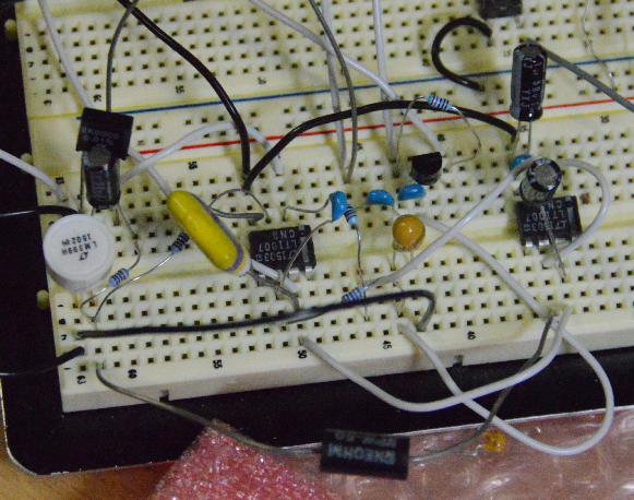
I’m showing this picture to give an idea about the actual physical construction, because that is important when PPM and nA are involved.
Here is the current schematic:

Description
The stability of U1, R1 and the input offset/noise of U2 are the important bits which determine the ultimate performance.
The C-field solenoid current will be approx 3.5 mA (= 7 V / 2000 Ohm)
U1 is a LM399 which has “typical” specification of 0.3 ppm/K and 7µV noise.
R1 is a Vishay S102J with 2 ppm/K.
U2 is a LT1007 with 0.6µV/K offset drift and 60nVp-p noise.
There are no filtering capacitors on U1’s output, which is outside the feedback loop, because any capacitor big enough to make a difference, would introduce temperature sensitivities far too big.
Filtering is provided by C1 which reduces U2’s gain to unity at high-ish frequencies and the R4+C2 low-pass filter.
The C-field solenoid and its wiring is only decoupled on the high side, with C4, where leakage current and capacitor tempco does not affect the current regulation.
All of these components are inside the feedback loop and normal components were used.
R2,R3,R6,C3 & U3 provide a stabilized powersupply to U1.
The zener in U1 has a series resistance of 1-1.5 Ohm, which means that a change in supply current of 1mA changes the output voltage up to 1.5 mV
The noise-budget is 40 µV (= 20 nA * 2000 Ohm), so it follows that the zener current must be regulated to better than 26 µA (= 40 µV / 1.5 Ohm)
For the 1-10 mA zener current that translates to a couple of percent which isn’t particularly hard to do.
In this case R3 develops about 1.75 V (= 3.5 mA * 500 Ohm), and via the low-pass filter (probably not needed) and U3 this turns into 1.75 mA through R2 and U1.
R2 and R3 are 5 ppm/K wirewound resistors, because I happened to have them. Regular 50 ppm/K metal film should be fine.
The bypass resistor R6 across Q1 bootstraps the entire circuit.
Performance
The circuit is very sensitive to parasitic loads at those circuit nodes where you can actually measure the performance.
For the plot below I used a 250 Ohm, 5 ppm/K resistor as C-field solenoid, and measured the voltage across it to deduce the current through it.
There are a large number of problems with that, starting with the resistance being 20 times larger than the “real” C-field solenoid and ending (probably) with it having same temp-co as R2 and R3, 800 times lower than the 4000 ppm/K of the copper wire in the real solenoid.
But with that caution:

The saw-tooth pattern is due to the air-conditioning.
Changing VCC between 20 V to 20.5 V and 19.5 causes an excursion of a few nA for about 3 seconds.
Conclusion
Well, it seems to work.
Next up: Find a way to build it into the HP5065A.
Along the way I found a very simple circuit in an old Burr-Brown App Note:
Make a precision current source or current sink
I havn’t done the math, but with a Vishay Z201 class resistor and maybe with a better reference than REF102’s 2.5 ppm/K tempco, that might be perfectly adequate.
The circuit doesn’t lend itself to the LM399 (or LTZ1000) style buried zener references due to the required external zener current regulator.
But if you want to do something like this, consider giving it a shot, David from the EEVBlog did, and it seemed to work for him.
phk