At my old house I had rigged up a 20 meter long wire antenna from my lab to a tree at the far end of the garden. Unfortunately, my new house lacked both suitable trees for the far end and a suitable and accessible place to mount the near end on the house. It did however have a very nice attic in which a LF loop antenna could be conveniently and comfortably located.
I spent some evenings researching loop-antennas and found a site in Italy where people are very serious about Radio Waves below 22kHz. My needs were a bit more modest than theirs, but I picked up their recommendation of the Analog Devices AD797 Op-Amp.
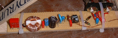
I wound a couple of loops and played around a bit in my lab until I got a circuit which I liked. It's pretty straight forward, apart from the power-supply filteringer where I went all-out, just in case.
Since my antenna was not going out into the elements, the physical aspect of the antenna was done using "the nearest bent nail" principles: A lid from a bucket of paint had a grove which was close to perfect for winding the coil, a couple of the sticks you get to stir the paint with, a bit of glue, a couple of nylon strips and it was done.
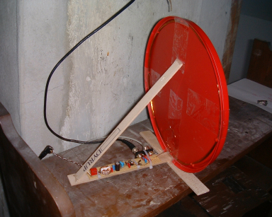
The nice thing about using a loop antenna is that it has a very distinct "null" on the axis through the center of the loop. I live only about 30km from a 300 kW long-wave transmitter Kalundborg Langbølge and I have found it very convenient to be able to turn the deaf side to the 243kHz signal which comes crashing in from the north.
From the antenna a surplus thinwire ethernet coax cable takes the signal all the way down to my lab in the basement.
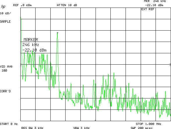
This is an averaged spectrum from 0 to 1 MHz. The longwave station is a dominant feature in the spectrum. The stuff above 500 kHz is not as far down as I could want, I may have to add a low-pass filter to avoid mirrors in the sampled data.
Here is the area up to 200 kHz captured in "MAX" mode, this is necessary to display the LORAN-C part of the spectrum in a usable way.
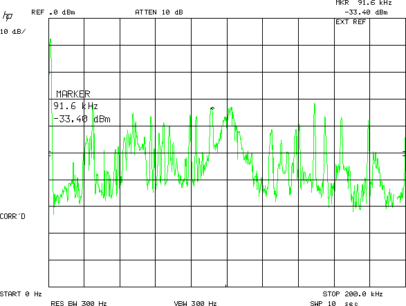
Finally a close up of the LORAN-C spectrum, I have not identified the signal under the marker, it is not unlikely that it could be one of dozens of switch-mode power-supplies in our house.
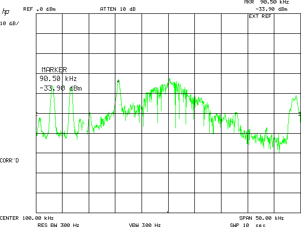
These plots are captured from a used HP8568B spectrum analyzator which I bought from W.J. Ford Surplus Enterprises some years ago. It has not been calibrated in ages, so take numbers only as an indication. The GPIB software is some stuff I wrote, it runs in userland under FreeBSD. I used the hp2xx program to convert from PCL to PNG format.