HP5065A Temperature Sensitivity
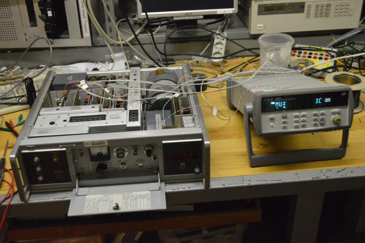
I found a HP5065A on eBay recently, and have started playing with it.
It is evidently quite sensitive to temperature, so I set out to find out why that might be.
My first idea was the C-field, if the current driving that isn’t incredibly stable, the frequency will obviously vary.
My first experiment was to measure the voltage over the current sensing resistor (A15R10 & A15R11) with my HP3458A, and bingo! It was not stable.
What’s more, the long term MVAR floor I had measured could be entirely explained by the C-field current noise I had measured.
I decided to try to get all the relevant data in one go and hooked my HP34972A up with four 10k NTC termistors and six shielded cables:
The termistors (twisted pair wire) measure the temperature of the OCXO, the Rb physics package, the C-field pot and the A15CR5 zener diode.
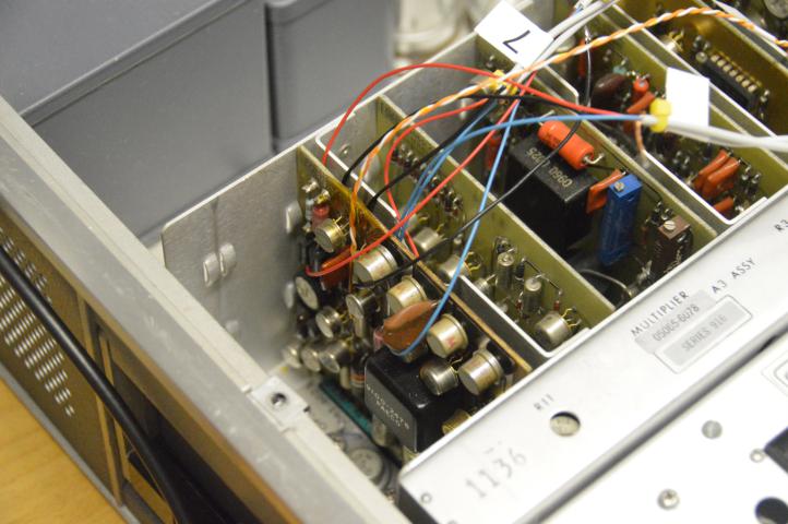
The six shielded wires probe the A15 assembly as follows:
The +20V supply voltage (top of R7)
The Zener voltage (CR5)
The high and low connections to the C-field coil (“1” and “9”)
The high and low connections to the C-field pot (two wires at bottom right)
Result: The zener is temperature sensitive
The A15CR5 ener diode is temperature sensitive at the 20 PPM/C level:

This is not good, that zener is supposed to keep everything rock-stable.
It is a 1N938, which was pretty much state of the art back when the HP5065A was designed, but the component list does not indicate if it was a selected part or just run-of-the-mill.
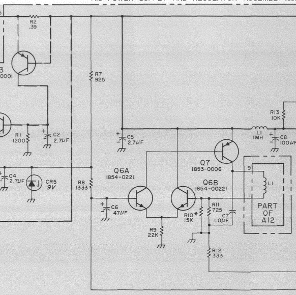
The 1N938 is driven with almost 12mA ((20-9V) / 925R) in the schematic above, and that may not be a good idea.
Later data sheets for 1N938 list 7.5 mA as the optimal drive current for zero temperature coefficient:
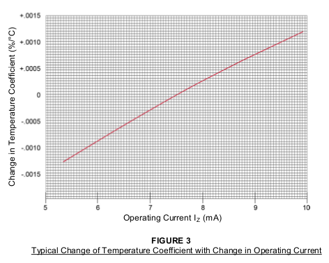
An obvious experiment would be to put a 2K trimmer in series with R7.
This also explains why it takes about an hour for my HP5065A to stabilize: the zener needs to reach a stable(-ish) temperature.
Result: The current regulator isn’t very good
When the HP5065A is switch to “LOCK” mode, the +20V supply drops a millivolt or so, and disconcertingly the voltage over the R10||R11 C-field current sensing resistors do as well:

I switched in and out of “LOCK” mode a number of times, and finally left it locked from 1000 seconds onwards
I am not entirely sure what’s going on here, but my theory is that Q7 simply isn’t up to the job.
The voltage across the C-field coil is only 56 mV which rides on top of 3.2 V across R10||R11.
This leaves 16+ Volts for Q7 to dispose of, and it looks like the noise from the +20V supply pretty much leaks straight through.
I have not done the math on this one yet, it may be below the radar, but I think not.
Possible remedies would be to put a pre-regulator in front of the current driver.
More radically one could design an entirely new C-field driver using a dedicated voltage reference. A good low noise op-amp can easily drive the C-field coil directly.
Conclusion - so far
At least for my HP5065A, it looks like the MVAR floor comes from temperature sensitivity in A15.
I’ll leave the data collection running overnight and as time permits I will mine for further insights, and add them to this page.
phk