New DC/DC converter PSU
I have modified the PSU along the lines I mentioned earlier, basically by installing a DC/DC converter:
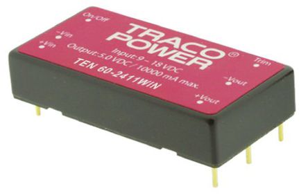
The specific model is TEN60-2415WIN from Traco Power.
I love living in the future: 60 Watt in a 1”x2” footprint and 92% efficiency with a 9-36 Volt input range.
Does that actually work ? Indeed it does:

This is after the HP5065 has locked, but not fully warmed up yet, and I still have the clock and various dividers disconnected.
If you want to run the HP5065 from +12 V you need to replace the 3A fuse for the EXT DC input with a 5A fuse.
What is even more impressive is that the output voltage swings only half a millivolt as the input voltage swings the full range:

And on the south-side of the +20V regulator on A15 there is very little correlation left, maybe 100 µV:

The gentle upward slope is due to the ongoing warmup.
The clearly visible ~50 second oscillation is probably the aircon.
Physical Installation
The physical installation is temporary.
That probably means it will stay this way forever, but I may decide to lay out a proper PCB, if it transpires that the +20V and -20V regulators need further improvement.
But until then:
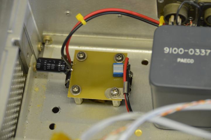
The DC/DC converter is equipped with the matching heat sink, and positioned upside down over the hole where the power transformer used to sit.
The small sqare PCB which covered the transformers terminals fit perfectly over the DC/DC converter using four random “hex-stags” I found in the junk-pile.
I put a 100µF/160V capacitor over the input and a 100nF film-cap over the output.
The output is wired through one of the mounting holes from the transformer and …
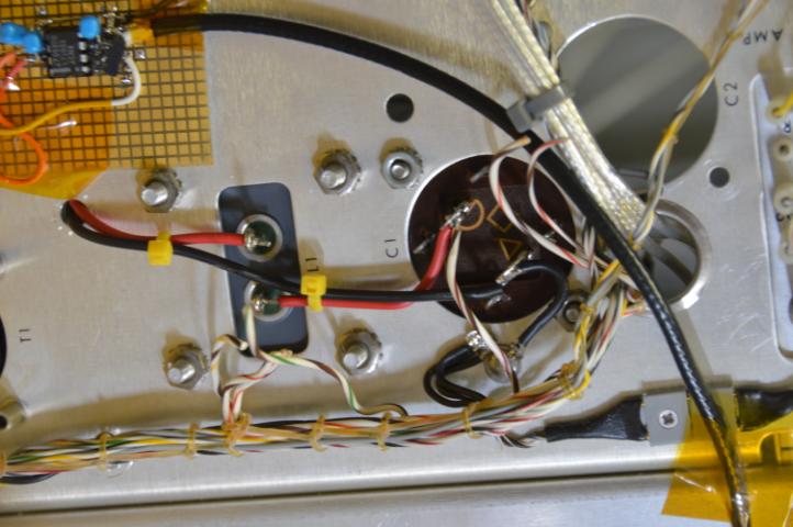
…goes through the “L1” 50mH inductor to the 1000µF capacitor, which the manual calls C1 or C4 or maybe both.
I am not at all sure that the L1 inductor improves the noise, but it was sitting right there, almost begging to be used.
It does cost about 1.5 {V} and I had to trim the TEN60 a bit upwards to compensate for this, to get enough headroom for the +20V regulator on A15.
The TEN60 uses quite large value resitors for trimming, and I fear that the tempco of the 1% resistor I found will bleed through, so I may decide to bypass L1 again, once I’ve done some noise measurements.
Note that the 2800µF capacitors are larger than the TEN60 specs allows.
From the capacitor, connection to chassis and to the +22V-30V rail.
I have not hooked up the OCXO pre-heater, but the “GRA + WHT-YEL-GRA” pair is right there if I ever decide to do so.
The small prototyping board is the experimental C-field driver
Now voltage variations in my labs +24VDC battery-backed supply will no longer disturb the HP5065A.
The saved electricty and heat, 5-10 {W}, around 50 {kWh/year}, is a nice bonus.
phk