I bought a small Proxxon MF70 router, modified for CNC use by Usovo, for various uses, amongst these isolation-routing of an occasional PCB.
After a few experiments I realized that the Z axis is a problem.
Either you spend a lifetime trying to get your PCB level, relative to your machines Z axis, possibly by planing a special jig for each PCB, or you set your bit to drill "deep enough", typically half a millimeter, which will wear out your bits in no time, and force you to use feature sizes in the mm range.
Given that you have a high-resolution device in front of you, the obvious solution is to probe the height of the copperlayer, and compensate the G-codes Z-coords accordingly.
People have started picking up on this idea, which is good, here are some links:
Gavilan Steinman's version for RepRap
My page about how you (manually) calibrate the horizontal parameters.
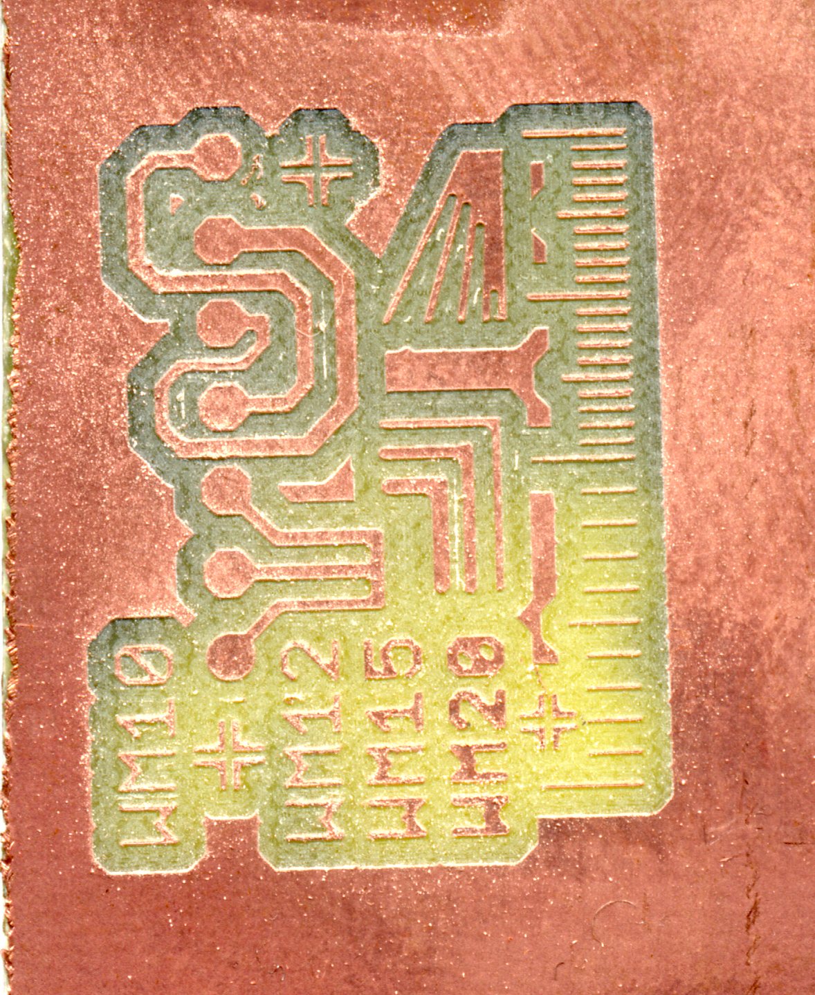
You bet. This is small test-PCB, scanned at 1200dpi:
Click on the picture to get the full sized version.
The "ruler" on the right has 1mm divisions at the bottom and 0.5mm divisions at the top half. The lines on the ruler are approx 0.1mm (= 4mil) wide.
You probably can not (right now).
It will take some work to make this proof-of-concept into a workable solution, and I neither have the time to burn, nor sufficient numbers of PCB's to route to justify it.
This web-page makes my prototype code available, but it will probably not work for you, because I just hacked it together on FreeBSD machine, and it will need to be made portable and cleaned up.
But if anybody in the CNC/PCB cross-over community wants to adopt this code, please do so, it is open source, you will find the sources below.
The absolutely simplest way to probe the height and avoid all the calibration constants relating to the bit-length, is to use the bit you will be routing the PCB with.
On my router, that works like a charm.
I connect a pin in the parallel port to the PCB, which I mount electrically isolated from the CCN-machine. When the bit touches the PCB, it shorts the surface to GND through the machine and EMC2 registers the probe as closed, provided you configure that pin in the parallel port as "probe input, inverting" in stepconf.
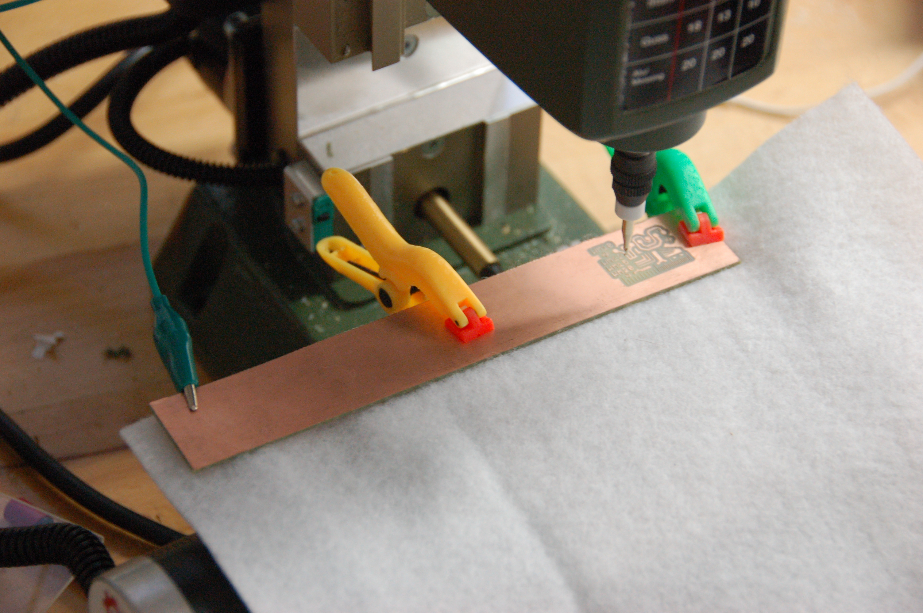
As you can see, I have done nothing in order to level the PCB, and I have put a piece of fabric under it, to isolate it from the X-Y table.
This piece of fabric also serves another purpose: If the probing mechanism does not trigger, your bit will be thrust into the board, non-rotating and likely destroy at least one of the two. The elacticity of the fabric buys you about 0.2 seconds longer time to hit the emergency stop.
(I test the probemechanism before I mount the PCB, by lifting it up to touch the bit during a probe (S38.2) operation, that way I know it works.)
The code reads in the output from pcb-gcode using a simple minded parser, which assumes that Z < 0 means "route this trajectory".
An elaborate, but not optimal, optimizer sorts the trajectory to minimize the lifts and moves and then outputs the G-code again, along with the probe/adjustment tricks.
The Gcode starts out by probing the work-area in a 4x4 grid, stores the measured heights in variables #2000... and proceeds to route the board, adjusting all Z-heights using these measurements.
The depth to be routed below the copper surface is set in register #3 and can, like a few other parameters, be changed after the G-code is produced.
Here is a snippet of the produced G-Code:
(XXX: bla bla bla)

(Things you can change:)
#1=12		(Clearance height)
#2=1		(Traverse height)
#3=-.1		(Route depth)
#4=-1		(Probe depth)

(Things you should not change:)
G21		(mm)
G90		(Abs coords)

M05		(Stop Motor)
G00 Z[#1]       (Safe height)
G00 X0 Y0       (.. on the ranch)

(probe grid)
(params: x y traverse_height probe_depth)
O100 sub
G00 X[#1] Y[#2] Z[#3]
G38.2 Z[#4] F25
G00 Z[#3]
O100 endsub

(PROBE[0,0] 0.000 0.000 -> 2000)
O100 call [0.000] [0.000] [#2] [#4]
#2000=#5063
(PROBE[0,1] 0.000 5.899 -> 2001)
O100 call [0.000] [5.899] [#2] [#4]
#2001=#5063
(PROBE[0,2] 0.000 11.798 -> 2002)
O100 call [0.000] [11.798] [#2] [#4]
#2002=#5063
[...]
(Gentlemen, start your engines)
M03 S1000
G00 X0 Y0 Z[#2] (.. on the ranch)

G00 Z[#2]
G00 X2.837 Y4.242
G01 X2.837 Y4.242 Z[0.178*#2000 + 0.103*#2007 + 0.263*#2006 + 0.456*#2001 + #3] F100
G01 X3.038 Y4.443 Z[0.150*#2000 + 0.097*#2007 + 0.295*#2006 + 0.458*#2001 + #3]
G01 X3.028 Y4.454 Z[0.149*#2000 + 0.096*#2007 + 0.294*#2006 + 0.461*#2001 + #3]
G01 X2.881 Y4.307 Z[0.170*#2000 + 0.100*#2007 + 0.271*#2006 + 0.459*#2001 + #3]
[...]
Notice the Z coords, those are bilinear interpolations between the surrounding four probe-points.
Long trajectories will be split into smaller pieces each interpolated for Z-height along the way. (remember to adjust number of fractions if you increase number of probe-points.).
The program consists of these three source files, which you can download here:
plt2g.h plt2g.c emit_gcode.cThe files are copyrighted but licensed under the following license:
/*
 * ----------------------------------------------------------------------------
 * "THE BEER-WARE LICENSE" (Revision 42):
 * <phk@FreeBSD.ORG> wrote this file.  As long as you retain this notice you
 * can do whatever you want with this stuff. If we meet some day, and you think
 * this stuff is worth it, you can buy me a beer in return.   Poul-Henning Kamp
 * ----------------------------------------------------------------------------
 *
 */
These three files will probably help you also:
queue.h Makefile testpcb.ngcNotice that queue.h is licensed under the 3-clause BSD license.
The testpcb.ngc G-code will probe and route a sequence of small lines of increasing depth, very useful to figure out the optimal depth and working conditions of your bits.
I have no idea how many points you need to probe a PCB to get good performance. It depends on the size obviously, and also on how flat it actually is. Making the number a parameter to the program is not a big deal, I just used a fixed-size array for convenience.
Ideally the G-code would do a sanity-check on the probed values, calculate the span (max-min), max neighbor difference and maybe standard deviation and tilt if they didn't look sensible.
There are two parameters in the code which affect the optimizer, one is the width of the bit, moves shorter than this will not actually lift the bit. The other is the cost penalty for lifting the bit, this is used to push the optimizer.
The optimizer does a decent job of sorting the trajectories, but its original purpose is not robust against the many nested loops which pcb-gcode produces, so total trajectory is typically 120-130% of optimal. Unless you need a good thesis subject, or just wants to play with a really nasty version of the Travelling Salesman Problem, I wouldn't waste time on it if I were you.
Ohh, and don't let the postscript confuse you, it's just a sneaky way to get debugging output out of the optimizer.
Thanks to John Johnson for the PCB-GCode program. It is a neat trick.
If somebody adopts this code, drop me a note and I will link to the civilized version at the top of this page.
I have posted a link to this page on the CNCzone forum, discuss it there.
Poul-Henning