HP5065A C-field potentiometer
My attempt to reference the C-field constant current generator with my Fluke 732A voltage reference instead of the CR5 zener didn’t improve stability a lot, so the search for temperature coeffients continue.
The two most important resistors for C-field stability are R10 and R11 which sense the current through the C-field coil:
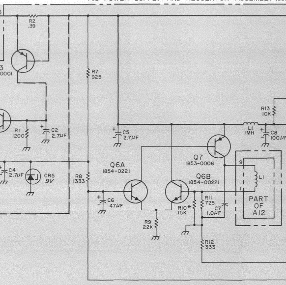
The little asterix next to R10 indicates that it is “factory selected”, but the note doesn’t say what they select it for.
My guess is that it is selected for the voltage of the CR5 Zener, which does not have a particularly tight specification for voltage.
In my case, R10 is a 11k 1% resistor, giving a combined resistance of 680R for R10||R11.
When I measured it by pulling A15 out, I found 677.4 Ohm and as the board cooled down, it rose to 677.8 Ohm over a few minutes.
That is a change of 600ppm for an unknown change in temperature.
Not good.
What is the criteria that R10||R11 and the CR4 zener voltage most fulfill?
I measured the Q6[AB] base voltages as a function of the C-field potentiometer and calculated the resulting C-field current, based on a nominal 680R R10||R11 combination:

This matches the box on page 8-64, which says that the current should be “2.5 to 6 mA”
As you can see the curve is not flat, this is deliberate, the Rb resonance does not depend linearly on the magnetic field, and the bend in this curve is what “calibrates” the C-field pot to be linear in frequency. (See TVB’s measurements of this here: HP 5065A Rubidium C-Field Resolution)
The line marked “Theory” is calculated as follows:
Lower_arm {Ohm} = (333 {R12, Ohm} + X {R6, Ohm})
# Note X = C-field pot resistance in Ohms = reading on dial.

Total {Ohm} = Lower_arm + 1333 {R8, Ohm}

V_q6a {Volt} = V_cr5 {Volt} * (Lower_arm {Ohm} / Total {Ohm})

I_L1 {A} = V_q6a {Volt} / 680 {R10||R11, Ohm}
# Note 680 Ohm = 725 Ohm (R11) parallel with 11000 Ohm (R10)
That’s a pretty good match.
Looking at the curve, and taking into account that the C-field setting 250 is used for the calibration, I think it is a pretty good guess that R10 is selected for 4mA C-field current when the C-field pot is set to 250.
If that is true, then the optimal value of R10||R11 is 76 times the reference voltage.
Various notes
Something bad clearly happens around 700 on the pot, looks like a loose connection but could also be instability in the circuit.
I also measured this curve with the Fluke 732A reference, the higher 10V reference means that R10||R11 should be 770R to replicate these currents.
The offset between the two curves is Q6[AB] not being well matched. The difference is on the order of 45 mV which means replacing them with pretty much any op-amp would be an improvement.
So a recipe for a new circuit at this point sounds like: LT1021 voltage reference, decent op-amp, low temp-co resistor(s) to replace R10||R11.
phk